Youtube Video (copy URL)
KEEPVID.COM (paste youtube URL)
Download FLV (flast so will work in Indesign)
In Indesign: File/ Place/ (the file)
............
When ready to save at the end of creating my whole document: File/ Export/ Adobe PDF interactive/ OK
2 January 2012

Sketchup - CUTTING SECTIONS through model
Cut Section
Tools, section plane. Make a vertical plane to snap the model I've made to if I want to cut a section at a particular interval.
Move into position, then export the section: File/ Export/ .DWG
Open in Autocad or Revit
Tools, section plane. Make a vertical plane to snap the model I've made to if I want to cut a section at a particular interval.
Move into position, then export the section: File/ Export/ .DWG
Open in Autocad or Revit
Creating a FLY THROUGH Animation in Blender
To animate a 3D Blender Model, take the following steps:
AVI Code. Save to Desktop/ 100% / ANIM / PLAY: STA - 1, END - 900 (Kept cutting off early)/ ANIM
Moving camera fly through : Grease - Draw, Sketch, RED...... Draw path, CONVERT TO PATH
TAB
Move Path up to Z Axis. Right click the end point of the line created (for the camera to follow)/ Shift S: Cursor to selection / 4 NODES OF RECTANGLE SYMBOL: Center Cursor / Click path line again / N:Change Z=0 prob -7.
Put camera on path (right click camera/ shift S/ selection to cursor// G Shift Z: Keeps locked to X&Y Axis
Select Path and $ NODE RECT SYMBOL Curve Path
Shift select both CAMERA then PATH
CNTL P // Follow Path (ALT+A shows it)
Slow it down// Right click Camera// 4 NODE RECT SMBL// Path Len:100 (make 250)
AVI Code. Save to Desktop/ 100% / ANIM / PLAY: STA - 1, END - 900 (Kept cutting off early)/ ANIM
Moving camera fly through : Grease - Draw, Sketch, RED...... Draw path, CONVERT TO PATH
TAB
Move Path up to Z Axis. Right click the end point of the line created (for the camera to follow)/ Shift S: Cursor to selection / 4 NODES OF RECTANGLE SYMBOL: Center Cursor / Click path line again / N:Change Z=0 prob -7.
Put camera on path (right click camera/ shift S/ selection to cursor// G Shift Z: Keeps locked to X&Y Axis
Select Path and $ NODE RECT SYMBOL Curve Path
Shift select both CAMERA then PATH
CNTL P // Follow Path (ALT+A shows it)
Slow it down// Right click Camera// 4 NODE RECT SMBL// Path Len:100 (make 250)
14 June 2011
Laser cutting experiment 1 in the workshop
The first experiment of laser cutting didn't work to plan. I had my pages oriented incorrectly (should be LANDSCAPE 812.8mm TALL, 475.2mm WIDE).
To use the machine, I opened my corel file, made sure everything was rgb red (the corel red), barcode numbers only had a blue outline (no black anywhere!!!), each line was a single line, and hairline thickness. Then grouped it and window selected the image (CNTRL + G)/ File/ Print/ Selection/ Properties: MDF 3mm... this is what I used) ok/ Print.
Then I opened the laser program, made sure it was on my slide, then pressed PLAY BUTTON to print.

Couple of issues with the machine, but I just had to clean up my file.
Unfortunately in my first attempt I had miscalculated the site's contour heights and somehow did not scale them accordingly with my other site objects (ie - the sheds were too large).

To use the machine, I opened my corel file, made sure everything was rgb red (the corel red), barcode numbers only had a blue outline (no black anywhere!!!), each line was a single line, and hairline thickness. Then grouped it and window selected the image (CNTRL + G)/ File/ Print/ Selection/ Properties: MDF 3mm... this is what I used) ok/ Print.
Then I opened the laser program, made sure it was on my slide, then pressed PLAY BUTTON to print.

Couple of issues with the machine, but I just had to clean up my file.
Unfortunately in my first attempt I had miscalculated the site's contour heights and somehow did not scale them accordingly with my other site objects (ie - the sheds were too large).

11 June 2011
Laser Cutting the Site Model - Process
The next thing on my weekly 'To Do' list is to laser cut a site model (roughly to the same scale as my bar web 3D prototype).
It was a long and involved process going from Blender, to Revit, to AutoCad, to Corel Draw.
Steps:
1. Cut sections in BLENDER at 3 meter intervals (using 3mm ply sheets). I imported the model into Revit, measured the distance between the cliff and river (was approximately 30 meters) then worked backwards (needed 10 sections cuts horizontally etc.)
The same principle was applied to the story bridge (vertical sections), and my important shed buildings on site.

To cut a section in Blender: join the object all together first (p)/ make a plane/ select the object/ cursor to selection (shift+S)/ and move the plane into the position where I want it cut for a section..... then Scripts/ Object/ Cross Section/ Yes: fill objects...... then export this.... Scripts/ Export/ Autodesk.DXF
2. Import sections into AUTOCAD (open the .dxf file). These are to be scaled up in CAD or REVIT to the size I want cut. I then had 2 options: 1/ keep all of the lines on layer 0 so that they could be changed colour in Corel... or 2/ change the lines to be cut: RED, slightly etched: BLUE, large blocks of text and images: BLACK. (NOTE: COULD ALSO USE GREEN AS GUIDELINES AS THEY DON'T PRINT).
In AUTOCAD I also drew up a mock laser template for the machine and made sure my objects fit on those pages (400mm x 800mm) before saving them as the oldest possible Autocad file (AUTOCAD 2000.dwg).
3. Open the Autocad file in COREL DRAW, checked all lines were hairlines (pen nib tool, select hairline)/ fit all of the puzzle pieces onto my pages (leaving 5mm margins, 390mm x 790mm)/ made sure each piece was code labeled in blue/ then grouped the number to the piece (select both/ Cntrl+G)... then saved it.

It was a long and involved process going from Blender, to Revit, to AutoCad, to Corel Draw.
Steps:
1. Cut sections in BLENDER at 3 meter intervals (using 3mm ply sheets). I imported the model into Revit, measured the distance between the cliff and river (was approximately 30 meters) then worked backwards (needed 10 sections cuts horizontally etc.)
The same principle was applied to the story bridge (vertical sections), and my important shed buildings on site.

To cut a section in Blender: join the object all together first (p)/ make a plane/ select the object/ cursor to selection (shift+S)/ and move the plane into the position where I want it cut for a section..... then Scripts/ Object/ Cross Section/ Yes: fill objects...... then export this.... Scripts/ Export/ Autodesk.DXF
2. Import sections into AUTOCAD (open the .dxf file). These are to be scaled up in CAD or REVIT to the size I want cut. I then had 2 options: 1/ keep all of the lines on layer 0 so that they could be changed colour in Corel... or 2/ change the lines to be cut: RED, slightly etched: BLUE, large blocks of text and images: BLACK. (NOTE: COULD ALSO USE GREEN AS GUIDELINES AS THEY DON'T PRINT).
In AUTOCAD I also drew up a mock laser template for the machine and made sure my objects fit on those pages (400mm x 800mm) before saving them as the oldest possible Autocad file (AUTOCAD 2000.dwg).
3. Open the Autocad file in COREL DRAW, checked all lines were hairlines (pen nib tool, select hairline)/ fit all of the puzzle pieces onto my pages (leaving 5mm margins, 390mm x 790mm)/ made sure each piece was code labeled in blue/ then grouped the number to the piece (select both/ Cntrl+G)... then saved it.

10 June 2011
Hardening the 3D Rapid Prototype
Once the models had been baked and dried slowly in the oven, they had to be hardened with a fixing agent.

The thicker concert shell was fine just apply 1 layer of the glue to (making sure not to go over any area twice or else it smudged). However, considering the web model was a lot finer, it had to be firstly drenched in glue hardener, quickly dried with the cool air gun, then resprayed with a sea salt water base mix to make it more rigid.

The thicker concert shell was fine just apply 1 layer of the glue to (making sure not to go over any area twice or else it smudged). However, considering the web model was a lot finer, it had to be firstly drenched in glue hardener, quickly dried with the cool air gun, then resprayed with a sea salt water base mix to make it more rigid.
2 June 2011
3D Prototype in Oven
Here is the update of the 3D prototypes live from the drying oven! They ran out of hardener but hopefully by next week it'll all be applied and they'll be right for me to take home.

The web worked nowhere near as well as the shell which is ironic considering I applied the same thickness of 5mm to both... yet the web came out at about 2mm?

The shells are great and look really sturdy which I think is a product of it being one plane (I saw many other models similar to my web thrown in the bin as they broke)


The web worked nowhere near as well as the shell which is ironic considering I applied the same thickness of 5mm to both... yet the web came out at about 2mm?

The shells are great and look really sturdy which I think is a product of it being one plane (I saw many other models similar to my web thrown in the bin as they broke)


1 June 2011
3D Models in REVIT, SOLID WORKS, Z PRINT & 3D RAPID PROTOTYPER
This week was a huge experimentation one trying out Revit, Solid Works, Z Print and the 3D rapid prototypes in the industrial workshop.

REVIT
Steps of how to bring blender model into revit and scale it up to be able to cut sections through etc. below:
1 - Bring model into revit (import)
2 - Look on google maps to gauge the scale of the site and measure something (I measured the story bridge was 30m wide).
3 - Back in Revit, draw a ML (model line) on the floor plan at 30 000 (as have set it up in mm)
4 - Scale up the model according to this by: select model/ modify/ scale/ click the 3 following points (1. edge of bridge., 2. other edge of bridge that I want to stretch to the 30 000 mark., 3. point where I want the model scaled up to which is the 30 000 mark).
This made for some interesting sections, but they were cluttered with trees etc.
SOLID WORKS
The workshop informed me that I had to pass the blender file through solid works before it would successfully print in the rapid prototyper (powder)... which didn't turn out to be the case! But I learnt a lot in the process.
I started by fixing up the faces of my imported STL file in Solid works so that it would print the 3D form properly. I spent ages and was told that I wasn't allowed to use the whole cone shape for my stage shell, but had to shell it to waste less powder before sending to print. This defeated me stitching it up in Blender in the first place (!!!!!!) but at least I got to practice my facing skills in Blender so wasn't a waste of time.
The way to thicken the shell in solid works was to 1/ select the outside faces of the shell I wanted to form together (as an outside surface) and then thicken them. I selected feature recognition from the top tool bars/ thicken/ thick outwards 0.05 so that it would print to be 5mm thick. Then save as stl unit in meters.
For the intricate web, I spent hours trying to heal all to close up all the faces but I couldn't get them all healed. Then simon walked in and said I didn't need to do that anyway and could have just copied and pasted the shape straight into Z Print by literally dragging it straight in!

So that was that! And I'll go to pick up my models tomorrow to see if they work. For the record, the lady next to me just modeled up a sketchup model and saved it as 3DS which was perfectly fine to once again COPY and PASTE straight into the Z Print file without converting it at all! This then fills up a box on the screen with all the models to print in the overnight session.
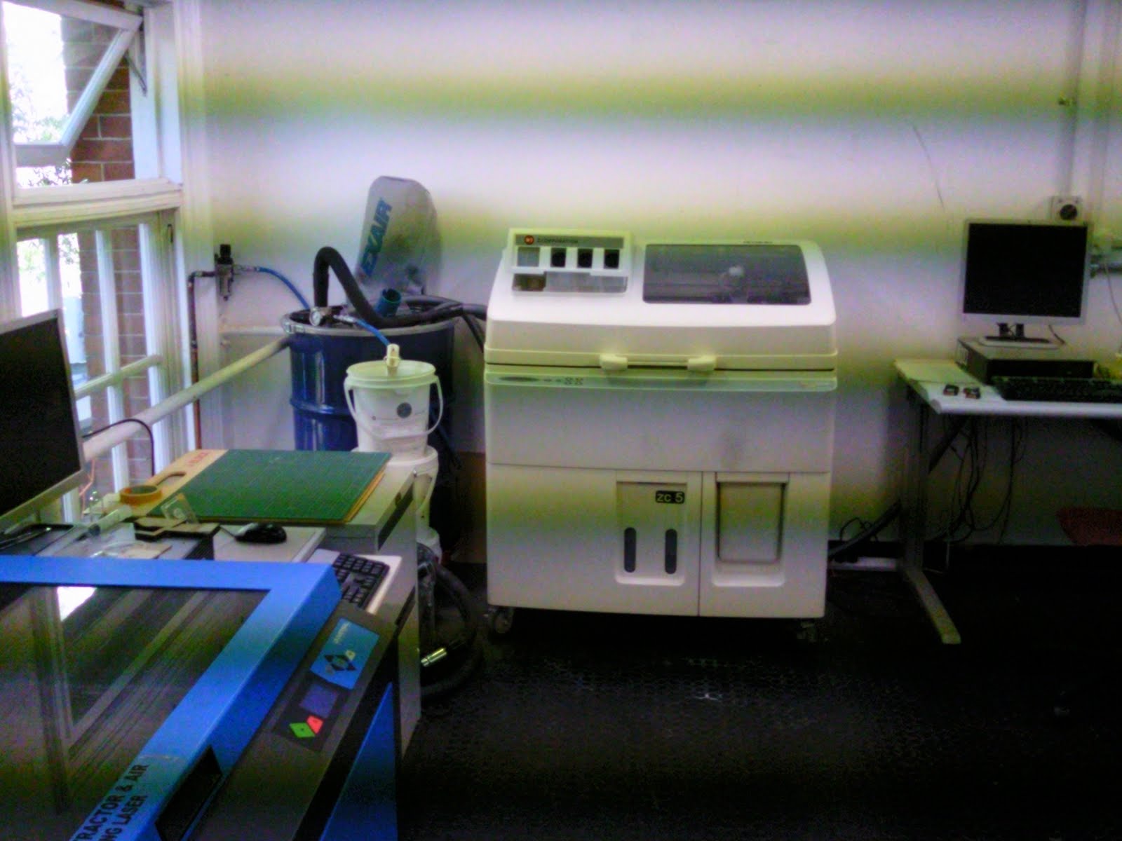
Below is a picture of the 3D rapid prototyper:

The white powder that forms our models looks like this:


REVIT
Steps of how to bring blender model into revit and scale it up to be able to cut sections through etc. below:
1 - Bring model into revit (import)
2 - Look on google maps to gauge the scale of the site and measure something (I measured the story bridge was 30m wide).
3 - Back in Revit, draw a ML (model line) on the floor plan at 30 000 (as have set it up in mm)
4 - Scale up the model according to this by: select model/ modify/ scale/ click the 3 following points (1. edge of bridge., 2. other edge of bridge that I want to stretch to the 30 000 mark., 3. point where I want the model scaled up to which is the 30 000 mark).
This made for some interesting sections, but they were cluttered with trees etc.
SOLID WORKS
The workshop informed me that I had to pass the blender file through solid works before it would successfully print in the rapid prototyper (powder)... which didn't turn out to be the case! But I learnt a lot in the process.
I started by fixing up the faces of my imported STL file in Solid works so that it would print the 3D form properly. I spent ages and was told that I wasn't allowed to use the whole cone shape for my stage shell, but had to shell it to waste less powder before sending to print. This defeated me stitching it up in Blender in the first place (!!!!!!) but at least I got to practice my facing skills in Blender so wasn't a waste of time.
The way to thicken the shell in solid works was to 1/ select the outside faces of the shell I wanted to form together (as an outside surface) and then thicken them. I selected feature recognition from the top tool bars/ thicken/ thick outwards 0.05 so that it would print to be 5mm thick. Then save as stl unit in meters.
For the intricate web, I spent hours trying to heal all to close up all the faces but I couldn't get them all healed. Then simon walked in and said I didn't need to do that anyway and could have just copied and pasted the shape straight into Z Print by literally dragging it straight in!

So that was that! And I'll go to pick up my models tomorrow to see if they work. For the record, the lady next to me just modeled up a sketchup model and saved it as 3DS which was perfectly fine to once again COPY and PASTE straight into the Z Print file without converting it at all! This then fills up a box on the screen with all the models to print in the overnight session.
Below is a picture of the 3D rapid prototyper:
The white powder that forms our models looks like this:

21 May 2011
Option 2 for tidying blender file ready for 3D rapid prototype exporting
As my bar feature structure is more complicated than the previous models, it was best to try and cut the face to prevent a tedious process of stiching it back together at the point where I sliced the figure.
I put the object and a large plane onto layer 3 so as to isolate them (M/ 3rd box/ and use the `~ key to get back the whole scene)... I then moved the plane up to where I wished to cut the shape sectionally. Then I selected the object SHIFT+ the plane/ W/ Difference/delete and you're meant to be left with the cut shape desired.

This appeared to be working well. However when I applied the normals checking process to this object, I noticed it was chaotic with normals and faces as seen below:

I also started to notice gaps in the facade, but was struggling to find the actual vertices to stich it back together as previously done in the first 2 models. I will go and see Simon in the workshop about this next week.
I put the object and a large plane onto layer 3 so as to isolate them (M/ 3rd box/ and use the `~ key to get back the whole scene)... I then moved the plane up to where I wished to cut the shape sectionally. Then I selected the object SHIFT+ the plane/ W/ Difference/delete and you're meant to be left with the cut shape desired.

This appeared to be working well. However when I applied the normals checking process to this object, I noticed it was chaotic with normals and faces as seen below:

I also started to notice gaps in the facade, but was struggling to find the actual vertices to stich it back together as previously done in the first 2 models. I will go and see Simon in the workshop about this next week.
20 May 2011
Converting Blender Model into STL format for 3D rapid prototyping
The first thing that had to be done with my stage model mounds was to stitch their faces up entirely so that I would produce a solid mound for both pieces.
This was done by being in edit mode. Have the magnet icon activated/4 vertices selection button on/ E (extend vertices down to a common flat base distance)/ Z/ CNTRL+hover over vertice I want to pull my vertice down to it's position in the z axis.

This was done for all vertices at the base and then they were stitched together using faces (SHIFT+select up to 4 vertices then F (faces)).
I then had to check that all of the normals were facing outwards so as to be able to be 3D rapid prototyped. This was done in edit mode of the object/ Mesh Tools More/ N size:1.5/ have Draw Normals selected. Be in face selection mode/ right click on the face that has the normals facing inwards/ EDIT button (4 vertices in square)/ Mesh Tools/ Flip Normal. Repeat for all faces like this.

This was done by being in edit mode. Have the magnet icon activated/4 vertices selection button on/ E (extend vertices down to a common flat base distance)/ Z/ CNTRL+hover over vertice I want to pull my vertice down to it's position in the z axis.

This was done for all vertices at the base and then they were stitched together using faces (SHIFT+select up to 4 vertices then F (faces)).
I then had to check that all of the normals were facing outwards so as to be able to be 3D rapid prototyped. This was done in edit mode of the object/ Mesh Tools More/ N size:1.5/ have Draw Normals selected. Be in face selection mode/ right click on the face that has the normals facing inwards/ EDIT button (4 vertices in square)/ Mesh Tools/ Flip Normal. Repeat for all faces like this.

MY FINAL 5 WEEK DEVELOPMENT PLAN (from last week's class)
WEEK 1
Make changes to my model according to Florian's feedback from Assignment 2.
This includes:
Good
• good presentation
• great diagrams
• the process worked well in helping us understand
• good details and understanding of the tectonics
Bad
• the rendered images are too black
• get rid of the fence
• morph a shape over the shed you’ll use for the bar so it ties in with the stage shape
• sound protection for the apartments
WEEK 2
Have a 3D rapid prototype done (modified experiment)
WEEK 3
Have a laser cut prototype done (fine to be the same experiment, just try this technology)
WEEK 4
REVIT documentation completed
WEEK 5
A week to do final panels, fly-throughs, print 1 day earlier than due, and powerpoint in Indesign (animations must work!!!).
Make changes to my model according to Florian's feedback from Assignment 2.
This includes:
Good
• good presentation
• great diagrams
• the process worked well in helping us understand
• good details and understanding of the tectonics
Bad
• the rendered images are too black
• get rid of the fence
• morph a shape over the shed you’ll use for the bar so it ties in with the stage shape
• sound protection for the apartments
WEEK 2
Have a 3D rapid prototype done (modified experiment)
WEEK 3
Have a laser cut prototype done (fine to be the same experiment, just try this technology)
WEEK 4
REVIT documentation completed
WEEK 5
A week to do final panels, fly-throughs, print 1 day earlier than due, and powerpoint in Indesign (animations must work!!!).
19 May 2011
Shed object experiments - fluid simulation of water #6

Slightly moving the structure to take up less of the pathway and heritage building next to it.
Shed object experiments - fluid simulation of water #5
While the structure fitted in with the strong geometric triangular form of the story bridge's cross bracing above, when considered in context of the site, and particularly the grass mounds intended for landscaping of the concert venue's seating and stage/sound built form, I decided to apply a modifier to achieve a more organic form.


This looked terrific and could be a really interesting structure for patrons to sit under inside the shed as well as an indication of its presence externally. Perhaps people could crawl up into that area to sit under with friends as another indoors option to sitting outside. The flood could be timber and they could sit up against cushions and see outside through glazing. The bar could be to the left of the building in this image.


This looked terrific and could be a really interesting structure for patrons to sit under inside the shed as well as an indication of its presence externally. Perhaps people could crawl up into that area to sit under with friends as another indoors option to sitting outside. The flood could be timber and they could sit up against cushions and see outside through glazing. The bar could be to the left of the building in this image.
Shed object experiments - fluid simulation of water #4
As previously stated the form needed to be moved out of the arch way and scaled down so as to respectfully fit into the site.
I then applied a plastic mesh like effect we learnt in class by selecting the water form object/ Z (wireframe) / scripts/ mesh/ solid wireframe/ ok (and maintained the default thickness as when increased it to 2 it took over the the whole site).

I then applied a plastic mesh like effect we learnt in class by selecting the water form object/ Z (wireframe) / scripts/ mesh/ solid wireframe/ ok (and maintained the default thickness as when increased it to 2 it took over the the whole site).

Shed object experiments - fluid simulation of water #3

The fluid was captured and frozen in a mesh from by selecting it, then ALT+C (delete the existing form). This can then be tabbed into for edit mode to alter it's structural form.
Shed object experiments - fluid simulation of water #2
In stills the video was caught in the following format before modifiers were added. The problem here is that the shape blocks the critical vista point from the path above between the bridge's arch and so this doesn't fit appropriately with the site.


Image below taken from mural walkway at top of cliff under the bridge which is frequented by many pedestrians and bike traffic hourly.


Image below taken from mural walkway at top of cliff under the bridge which is frequented by many pedestrians and bike traffic hourly.

Shed object experiments - fluid simulation of water #1
The first fluid simulation (nothing changed changed) to come up with a roof shape that is morphing over the sheds. This is to represent rain falling down onto the site in its subtropical climatic site of brisbane and to see how this interacts with the iconic story bridge above.
Adjusting project in accordance with crit feedback
In accordance with the crit feedback, I have altered my model to adjust lamp settings (changed to sun and reduced the luminance via energy rating value below 1). Also changed the background to black and deleted the fence lines through editing faces. What I discovered is that I actually had two models inserted into my composition and this was causing issues with lighting of my stage in the rendered images. So I selected the top model/ tabbed into edit mode/ W/ remove doubles.
I also noticed a few issues with the ground level being deleted. After no avail with face stitching, I created a base plane to work with for simulations.

I also noticed a few issues with the ground level being deleted. After no avail with face stitching, I created a base plane to work with for simulations.

12 May 2011
Feedback from Florian about assignment 2
Great experiments and has come up nicely for this point. Remove the fence between the venue and the existing heritage buildings however and landscape this more effectively. Also maybe use another experiment to interact with the existing sheds if I am proposing to use these as they don't look like a unified space. Perhaps drape a cloth off the shed and this creates an undercover walkway or morph a shape into the building...
Sunday afternoon jazz sessions at UNDERGROUNbD
Here's a snippet of the vibe at one of the weekly Sunday afternoon jazz sessions proposed for the UNDERGROUNbD, Howard Smith Wharves.


Subscribe to:
Posts (Atom)